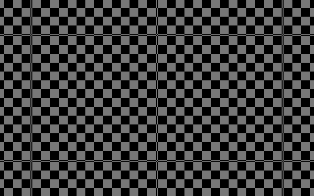
How do I get rid of this weird stretching present on the texture as it’s drawn?
I put in a tilemap to serve as a general-purpose background (mainly for the lighter VRAM usage), but I noticed the dither pattern is stretched to where it’s not uniform.
Here’s what the background looks like as a tilemap:
If anyone’s interested, here’s the shader code used for the tilemap:
shader_type canvas_item;

// The texture used by the shader.
uniform sampler2D fadeLevel: repeat_enable, filter_nearest;
// Controls which part of the texture is displayed.
uniform vec2 fadeAtlas;
// Centers UV coordinates based on number of subtextures.
uniform vec2 fadeAtlasUV;

void fragment() {
	vec4 baseTexture = texture(fadeLevel, vec2(fadeAtlas.x + (UV.x * fadeAtlasUV.x), fadeAtlas.y + (UV.y * fadeAtlasUV.y)));
	COLOR = baseTexture;
}
Is that sprite a single sprite? With or without repeat texture?
My guess would be the whole sprite is mapping from 0..1 for its UVs, while each tile is 0..1 for the tilemap, so the tiles are “zoomed way out” and you’re seeing the resulting roundoff distortion.
The core of this is taking the UV for the given fragment and using that to sample from the fadeLevel texture, restricting it to a subsection by adding an offset (fadeAtlas) and scaling the UV down (* fadeAtlasUV).
First of all, filter_nearest on the texture is going to give you noise like this when it’s pulling a small number of fragments out of a larger image. “nearest” in this sense means “round off to the nearest texel center”, so if the UV winds up dead in the middle between a black texel and a white texel it’ll pick one of them rather than giving you grey. Enabling mipmaps would probably help a lot too.
Second, I’m assuming the source atlas texture for this is fairly large? You might try making a source texture whose atlas region is closer to the size you’re actually drawing.
Though, third, if this is a tilemap background, unless you’re planning on scaling this or something you can just bake the image you want into a tile and fill the tilemap with that; a shader is kind of overkill here unless you’re planning on doing something funky with animated textures or something.
First of all, filter_nearest on the texture is going to give you noise like this when it’s pulling a small number of fragments out of a larger image. “nearest” in this sense means “round off to the nearest texel center”, so if the UV winds up dead in the middle between a black texel and a white texel it’ll pick one of them rather than giving you grey. Enabling mipmaps would probably help a lot too.
Yeah, that makes a lot of sense; although removing filter_nearest results in a different (albeit relatively minor) problem, due to the paletteSwap shader used:
Second, I’m assuming the source atlas texture for this is fairly large? You might try making a source texture whose atlas region is closer to the size you’re actually drawing.
The texture used for the shader is about one tile wide and ten tiles tall:
I guess it is quite tall for a 16x16 tile…
Though, third, if this is a tilemap background, unless you’re planning on scaling this or something you can just bake the image you want into a tile and fill the tilemap with that; a shader is kind of overkill here unless you’re planning on doing something funky with animated textures or something.
I suppose I could either A.) update the texture used in the shader or B.) fill the tilemap with the appropriate tiles.
I tried updating the texture used in the shader, and found that the problem is the texture is far too small for the tiles to be drawn like the sprite. This will need to be baked into the tileset itself.
The thin lines are where the tiles meet, so if I could make those as thin as possible and make the pattern appear seamless like in the sprite, then it should be good to go. I may need to swap out the texture that’s currently being used to aid with this.
I modified my shader to allow for UV manipulation:
shader_type canvas_item;

// The texture used by the shader.
uniform sampler2D fadeLevel: repeat_enable, filter_nearest;
// Controls which part of the texture is displayed.
uniform vec2 fadeAtlas;
// Centers UV coordinates based on number of subtextures.
uniform vec2 fadeAtlasUV;
// Shifts UVs by a certain amount.
uniform vec2 UVOffset;
// Scales UVs by a certain amount.
uniform float UVScale;

void fragment() {
	vec4 baseTexture = texture(fadeLevel, vec2((UVOffset.x * fadeAtlasUV.x) + fadeAtlas.x + (UV.x * fadeAtlasUV.x * UVScale), (UVOffset.y * fadeAtlasUV.y) + fadeAtlas.y + (UV.y * fadeAtlasUV.y * UVScale)));
	COLOR = baseTexture;
}
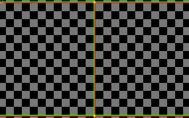
Then after toying with UVOffset and UVScale on the CPU side for a bit, I landed with the respective values of (−0.0625,−0.0625) and 1.125, leaving me with this:
I’m glad that I got this resolved, but with how the texture goes past the cell boundaries, I can’t help but feel the solution I came up with is esoteric.
It makes me wonder if there’s a way to align the texture with the cell boundaries…