As a newcomer to Godot and to aquaint myself more fully with it, I will be spending time on the GoTut https://www.gotut.net/ tutorial series (which looks very comprehensive) before proceeding any further with this project.
1 Like
Recently, whilst searching through my archives of year 2010 a.d., I came across an early version of my SciTechPlayroom in which I had used DirectX and PhysX. One of the projects I had progressed quite well with was the building of interactive Meccano models. This had required me to build up a collection of virtual 3D Meccano partsin the form DirectX .x files.
By the way, actual ‘Meccano’ was a very popular British modelling toolkit consisting of a vast range of metal parts from the simple Outfit No.1 to the very advanced Outfit No.10 ( see [https://alansmeccano.org/] for history and detail, if you are interested)
I will be converting these old .x files into Wavefront .obj mesh files which can be easily dropped into the Godot Editor for use by my SciTechPlayroom project.
As a start, here is a short video showing some of the parts, together with an operating Meccano electric motor driving a set of interlocking rigidbody gearwheels
My plan is to build a series of interactive virtual Meccano mechanisms demonstrating how the various parts can be used. I am really enjoying the ease by which the Godot Editor and GDscript are enabling me to do this.
3 Likes
This thing is coming out real good! does the gears really work!
Seems like we can create an ultra-realistic car without using any raycast or invisible wheels : D
btw are you using Jolt?
I am using the version of Godot which inclusively uses Jolt alone.
I’ve set up the gearwheel rigidbodies so that each tooth of a gearwheel is a separate collider. Hence they mesh with those of other gears very easily… all through the power of the physics engine alone!
For example, the drive pinion has 19 teeth and it is meshed to a 57-tooth gearwheel. This gives 3::1 ratio. The gear shaft is fixed to the 57-tooth gearwheel and therefore drives a further 25-tooth pinion which meshes with a 50-tooth gearwheel, a 2:1 ratio.
Thus, there is an overall 6:1 ratio, and the final output is a six times reduction in inital speed of the motor, and a six times increase in torque.
3 Likes
With Xmas over and old year past, Ive been able to continue with my SciTechPlayroom project.
Using the lessons I learned from my rope physics experiments, I’ve been able to apply them to a motorised sprocket chain for driving sprocketwheels. This was a slow laborious process, but the Godot Editor and GDScript eased this a whole lot, and I’m quite happy with what I’ve accomplished to date.
This first video shows my initial testing in manipulating the chain over two sprocket wheels. The problem I had was in trying to join the two ends together to make a loop in real time

I eventually had to put together a pre-made loop of chainlinks using Godot’s Path3D function. The use of this loop is demonstrated in the following video

The sprocket teeth on the sprocketwheels are all CollisionShape3D nodes, as are all the links comprising the chain. Thus the chainlinks individually interact with the sprocketwheel teeth, forcing the wheels to rotate in either direction.
4 Likes
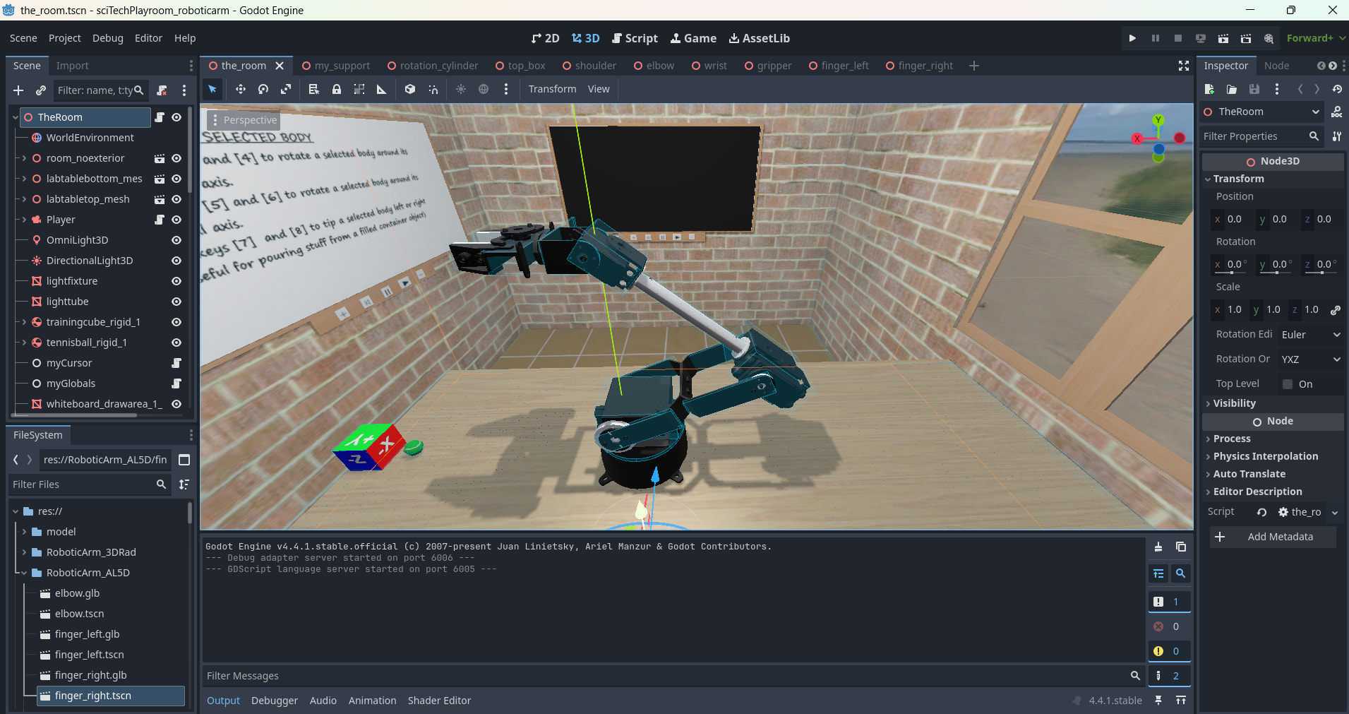
I’ve decided that the desktop needed something fun and which would also be a good test of 3D joints and interactivity. A robotic arm came to mind.
It had to be rigidbody-based, 6 degrees of freedom and programmable to do some simple tasks.
Fortunately, I already had in possession some .gbl robotic arm mesh model files, which I’ve convertd to Godot RigidBody3D types and laid out on the desktop, as shown below:

I’ve assembled these parts (unjointed) , in order to get a picture of how the final arm will look.
My next task over the coming weeks will be to add all the required joints and get the thing working (hopefully ![]() )
)
3 Likes
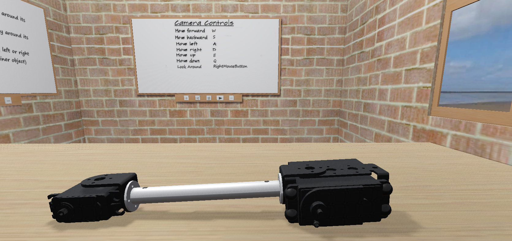
Ok, I’ve made a start at jointing up the main parts comprising the robotic arm.
I’m doing this starting from the bottom and working up.
Here is a screenshot of the seperate parts:
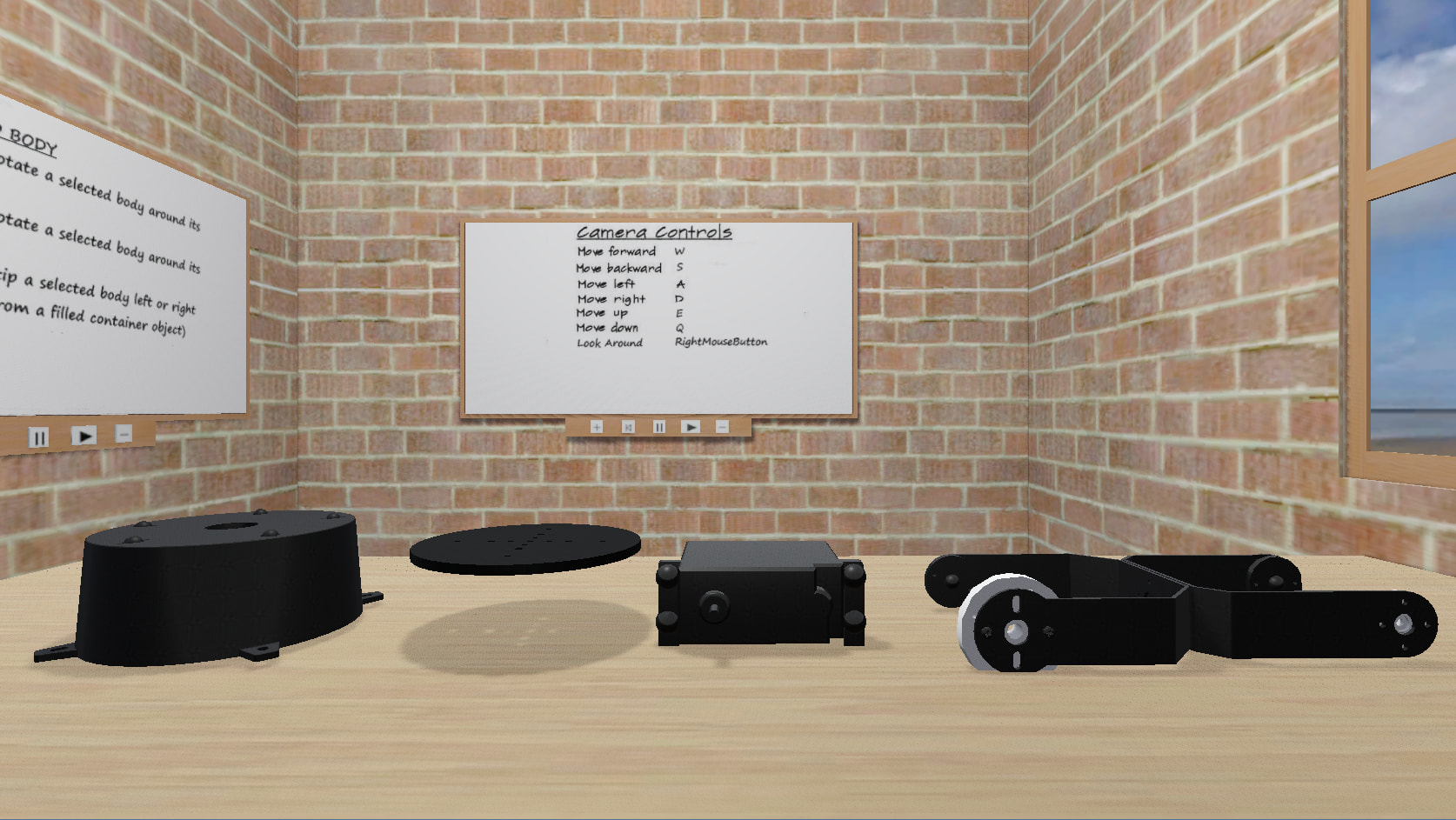
From the left, the parts are named as follows:
-
the staticbody ‘support base’
-
the rigidbody ‘rotating support disc’ which will be attached to the ‘support base’ via a Generic6DOFjoint3D set up to rotate around its local Y axis
-
the rigidbody ‘shoulder support’ which will be firmly fixed to the ‘rotating support disc’ via a Generic6DOFjoint3D set up as a fixed joint
-
the rigidbody ‘shoulder’ which will be attached to the ‘shoulder support’ via a Generic6DOFjoint3D set up to rotate on its local Z axis
Here is a video of me testing the jointed assembly using a small rigidbody cube helper which I can manipulate in realtime to push/pull the partly assembled ‘shoulder’ part.

So far, so good.
Now to continue with assembling the remaining parts.
1 Like
It probably would, but I have neither the time nor inclination to get into the latest VR. I am just happy pottering along with this little playroom project, and hopefully some newcomers to the use of 3D physics engines will be inspired to experiment.
At the moment, the masses used in the robotic arm are just thumbsucks based on the physical size and material density of the components.
2 Likes