What sets normals in a procedurally generated mesh?

Godot Version

4.4.1-stable

Question

I’m trying to create terrain for my map in a civ-esque game.
I generate a mesh at runtime, which I deform using noise in my vertex shader.
Up until now, I used the same noise texture with “as normal map” set, to create normals for the terrain.

I had wanted to try a different approach, so I stripped the setting of the normals from the noise texture. Here’s a picture of what this looks like in the game now, with the normals stripped out.


and:

Here’s my question:

I can see shadows, and I can see that normals exist on the mesh now. I’m not setting the normals anywhere. Nor in gdscript while creating the mesh, nor in the shader (the normal texture is removed, and no reference to NORMAL).
What is setting these normals?

The existence of shadows is not an indication that the material uses custom normals or a normal map. What about the current material makes you think you can see a normal map being applied? Have you tried verifying that this is actually the case?

Could it be that you’re conflating the vertex shader’s normal map with the vertex normals of the mesh?

Which method are you using to generate your mesh?


Let me know what you’re thinking.

Ah, I thought shadows meant normals were present.

In terms of mesh - its an ArrayMesh - I populate vertices etc to create a hexagon layout, and attach UV and some custom vertex info.

This is then fed into a MeshInstance3D, with an associated shader.

The shader then uses a noise texture along with some custom shaping logic to displace the y values of the vertices.


I guess a followup question I have. How should I go about computing normals?

Normals from noise texture:
Earlier in the project, I took my noise texture, duplicated it, and used it as a normal map. This caused some issues where the normal values changed between vertices, leading to incorrect normals.
Eventually I worked out this was due to there being more normal map pixels between each vertex in my mesh.
With a square mesh, this is easy to resolve, since you can just match the num of vertices on the x-axis to the number of pixels in your noise texture. With a hexagon, this is harder (but doable).
Furthermore - displacing the mesh isn’t done in a linear manner across the mesh. Mountain tiles have a pre-made shape associated with them + a different noise multiplier than say flatland tiles.

Computing normals:
Another approach I thought about was to compute triangle normals in the vertex shader and use those. Some reading suggested this will create worse visuals than a per-pixel normal calculation

I’m very open to suggetions/ideas on how to proceed on this?

Could you clarify how you define “incorrect normals”; and what you mean by normal values changing between vertices?


I’m going to disregard the rest of your questions about the procedural generation/application of normal maps. You’re trying to describe ways in which you can apply custom normals to your mesh but I am uncertain of the result you’re looking to achieve.

Generally speaking, you use normal maps to emulate a fine level of geometric detail by influencing lighting calculations. Mesh normals, on the other hand, directly determine the smoothness of the mesh by defining each vertex’s normal direction and, as such, defines the shaded appearance of the mesh’s faces.

As such, you could argue that a normal map’s main purpose is to emulate the lighting characteristics of realistic materials while mesh normals is a requirement to render your geometry’s lighting in a physically-based manner.


Perhaps I could be more concise.

  • What is the result you’re looking to achieve? Once I/we know that, we can proceed with finding the correct approach.
  • ArrayMesh has regen_normal_maps() which regenerates the normals for the mesh. Have you used this; and if so, why did it not work as you wanted it to?

There’s a nice YouTuber called Sebastian Lague who has done an entire series on procedural terrain generation. Have a look at it, particularly this part on normals:

Within my shader, I use 2 sources of noise - a high frequency noise texture for smaller details, and a smoother noise texture. These 2 noise textures are used to deform the vertices in the y dimension.

I then duplicate these noise textures, enable “as normal map” and sample the normal map in the fragment shader, to deduce what the normal should be at that point.

My mesh is an X/Y grid. I have 2X number of vertices along the x-axis, and 4Y on the y axis. Let’s say this works out to a grid of 500x1000 vertices.

My noise textures are 2048x2048. My understanding is that within the fragment shader, when I sample the noise textures, I could potentially go through 2 noise map pixels between each vertex.
So shading goes through 2 different “regions” because the normal changes, but the underlying terrain has not done this.

I grant you that I could definetly fix this by making the number of vertices match the number of pixels in the noise texture. Is this analysis correct?


On the subject of use regen_normals call - would that net the correct result, given that mesh displacement happens in the shader? I guess if I used a compute shader, fed the resulting vertex positions back to gdscript and then ran it?


What do I want to achieve?

I’d really like to reach a point where the normals across the mesh are correct, and where I can query the normal to figure out how steep the terrain is.

What I’d like to use this for is to determine where I should allow things like vegetation, snow, sand etc to settle, and where I shouldn’t. Terrain too steep? Snow won’t settle, so the underlying cliff should be visible.

Okay, I think I understand now. You’re using the ArrayMesh exclusively to generate the 500x1000 vertex grid, and these vertices are then displaced in the vertex shader based on a noise texture (height map).

What do you mean by “going through” 2 pixels/regions?

No, it’s not. I don’t know where you got this from.

You’re right. It would not yield the correct result in your setup. I was under the assumption that you generated your mesh on the CPU once and used the shader exclusively for fragment shading.

I see. I assume that your vague description of “correct” should be interpreted as: a normal map that overlaps the same noise texture used to displace the vertices.

I don’t see how this is even a problem. It should just be correct if you’re using the same UVs for vertex displacement and texture mapping.


Would it at all be possible for you to supply your current shader code? It’s a little hard to determine the exact problem without knowing your implementation.

Okay, so I think what’s happening is this:

I have a height texture that is 10x10 pixels.
I have a map that is comprised of 5x5 vertices.
I map UV to the X/Y position across the entire map - effectively saying that the vertex at location (x,y) has this UV value: (x/MAP_SIZE_IN_X, y/MAP_SIZE_IN_Y). In the example here, MAP_SIZE_IN_X == 5, same for the Y value.

This will give me a UV value in the range of 0 to 1, with let’s say the tile at position (1,1) having a UV of (0.2, 0.2).

In the vertex shader:
I lookup the height in the height map using the UV position, and get a value, lets say h0.
Moving to the next vertex over, at (0.4, 0.4) - I lookup the height again, and get a different value, h2.

In the fragment shader:
Since UV gets interpolated between points - and I’m using this UV to lookup the normal values in the “as normal map” version of my height map, I have this:

At UV (0.2, 0.2): I lookup the normal, get n0 which matches h0, great.
At UV (0.4, 0.4): I lookup the normal, get n2 which matches h2, great.
At UV (0.3, 0.3) - interpolated and doesn’t have a corresponding vertex: I lookup the normal, get n1 which doesn’t match h0 or h2 or h_interpolated, and it looks wrong.

At least I think this is what is happening. I apologise if I’m not clearly getting my point across, I’m very new to gamedev/shader work in general, and my use of terminology feels inaccurate.

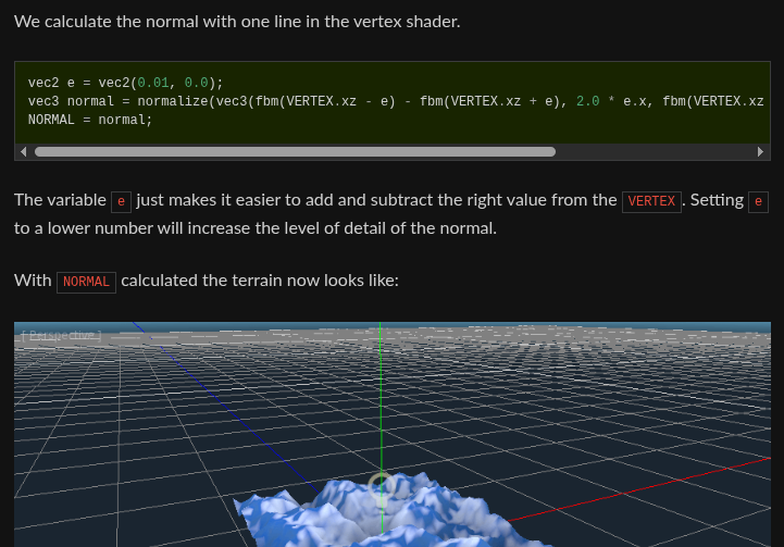
When I was researching all of this, I bumped into a similar problem in an old tutorial I read:

A few paragraphs down:

This still does not look how we want it to. The issue here is that the noise changes faster than the vertices do. So when we calculate the normal at the point of the VERTEX it does not align with what we see in the final Mesh. In order to fix this we add more vertices.

I think this is also what is happening to me!

Spot on. Because you lack knowledge, it’s near impossible to help you with your problem on a purely theoretical level (i.e. discussion over text). I asked you for concrete implementation details (e.g. code) but you still fail to provide it so I’m afraid that there’s nothing new for me to add.

As for the documentation you linked, there’s no mention of normal maps so I don’t see how that relates to what you’re trying to do. Either you don’t understand the article you linked, or you’re still conflating vertex normals with normal maps. All the article is saying, in the section you’re quoting, is that the mesh was too coarse (low resolution) to represent the high frequency detail in the noise texture. Therefore, the mesh resolution had to be increased to capture the detail.

This phenomena is related to the Nyquist-Shannon Sampling Theorem.


If there is something you don’t understand, you have to ask questions – not fake your own understanding. That may sound harsh but you have to be honest with yourself as much as anyone else.

from the same tutorial they provide a solution

In the vertex function, you can sample three Vertex points to find the slope of the surface. and pass it into the NORMAL, the shading will happen properly. You can however bake a normal map into a noise texture, but it is a little more cumbersome to setup, the trade off is that you can save the GPU some time. Both sampling and baking use the same 3 sample principle.

A third option is if you are using the SurfaceTool, there is a function to generate normals for you.

2 Likes