2D Polygon-based level design

Godot Version

Godot 4.2.2 stable

Question

I’m making a game based around destructible 2d polygons, using the Geometry2D.clip_polygons etc to interact with the polygons. One thing I’ve noticed is that there’s cleanup inherent to the functions - if you create a block that digs through a polygon as it moves, it will NOT leave a vertex for every frame it runs the clip function - the clip will clean up as it goes to keep the vertext count low. This is obviously generally a good thing.

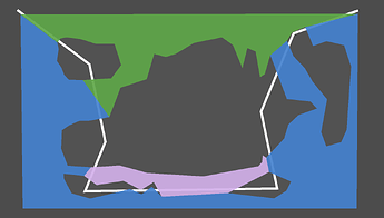
However, I can’t control it directly(?) and the cleanup is potentially destructive. Ultimately, I intend to draw polyline2D as outlines to the terrain polygons. I also need to be able to have ‘holes’ in the levels, to keep possibilities in level design open. In an attempt to prep for this I made the level as pictured :

The idea is to iterate through the vertices of the polygon and see that 3-4 and 11-12 are identical (a “seam”), then use that data to determine where and how to draw the outlines. However, with this setup, the first time clip_polygons is run, it will recognize that 3-4 and 11-12 are identical, seemingly merge those vertices, then return a polygon shaped like 1, 2, 12, 13, …1, as well as a polygon 4, 5, 6, 7, 8, 9, 10, 4 (the ‘hole’) as a result of the clip_polygons function.

Given that, my questions are as follows:

Is rewriting the clip_polygons function in C++ going to be a horrible pain in my butt and not a clean solution to my issue?

Is there some simpler way I should be setting up my project fundamentally, given that “Terrain with holes/voids” is a necessary part of level design?

Is “Polygons with holes/voids” actually possible, and I just haven’t learned how yet?

It’s been a few days - anyone have any ideas?

Is “Polygons with holes/voids” actually possible, and I just haven’t learned how yet?
Polygon2D does not support “holes”.

Polygon2D is an outline editor tool for rendering meshes. Outlines need to be converted to an actual mesh with triangles behind the scene for rendering and actual mesh polygons can not have holes.

The debug may not clearly show this because everything is just the same color but all your outlines are converted to mesh triangles to create the surfaces. The “holes” are just empty space with no triangles. They are not defined in an way because there is just nothing.

You can still do your “terrain” with outlines if you choose so but you can not use a single Polygon2D for the display. You need to create your own visualization or use multiple Polygon2D nodes for each returned outline of a Geometry2D clip operation.

1 Like

Gotcha. I’ve seen your name come up elsewhere when I was looking for solutions to this - I appreciate the response.

I’ll come up with a system for doing what I’d like to do with multiple polygons, then post that system here for future internet-travellers.

Here’s what I came up with.

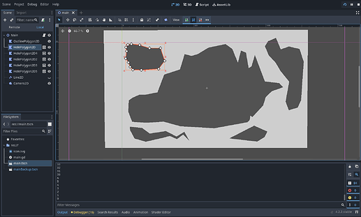
You start here. There are two types of polygons - one is the outline of the stage and just a big rectangle, the others represent holes. This is ultimately how I want to be able to design levels, so it seems like a sensible launch point.

Because “Polygons with holes” can’t be done, we’re gonna need to divide this into multiple positive shapes that form the terrain. The simplest way I could think of to do this (without doing it manually) is to draw a line through the terrain, indicating a seam, and compute vertices and polygons from that data. That looks like this :

From here, the basic premise is that the Line2D travels through each hole and, using Geometry2D, makes note of each time it ENTERS, and each time it EXITS a polygon. These values are each stored in an array and used to construct two major polygons, with the general concept of “Start at entrance vertex, go clockwise until you find an exit vertex, then repeat from the next entrance vertex in sequence”

You might notice that, in the example, this could not fill the entire space. There’s a segment in the middle of the level that neither of these major polygons could encompass. Any time the line re-enters a polygon it had entered before, it HAD TO HAVE left a polygon behind. In code I refer to these as “appendage” polygons, and they’re noted and constructed using similar methods to constructing the other two.

Beyond that, it was (and likely will be) just catching edge cases such as making sure it’s the LAST time the line exits the polygon that is stored, and that the same vertex cannot be stored as both an entrance and an exit vertex, etc.

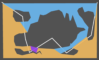
The end result is this:

or this :

or this :

Depending on how you want to live your life.

This topic was automatically closed 30 days after the last reply. New replies are no longer allowed.