Here’s what I came up with.
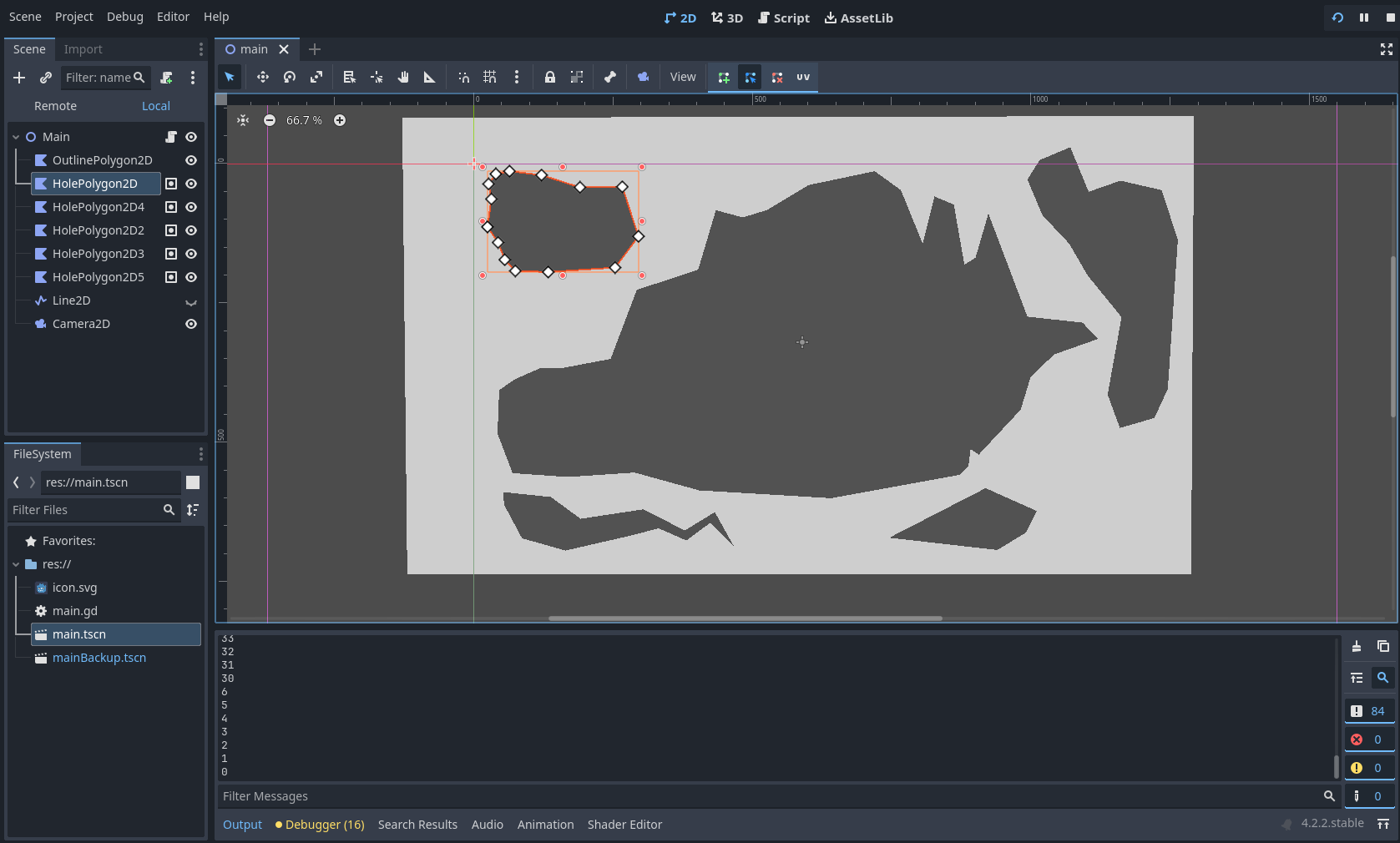
You start here. There are two types of polygons - one is the outline of the stage and just a big rectangle, the others represent holes. This is ultimately how I want to be able to design levels, so it seems like a sensible launch point.
Because “Polygons with holes” can’t be done, we’re gonna need to divide this into multiple positive shapes that form the terrain. The simplest way I could think of to do this (without doing it manually) is to draw a line through the terrain, indicating a seam, and compute vertices and polygons from that data. That looks like this :

From here, the basic premise is that the Line2D travels through each hole and, using Geometry2D, makes note of each time it ENTERS, and each time it EXITS a polygon. These values are each stored in an array and used to construct two major polygons, with the general concept of “Start at entrance vertex, go clockwise until you find an exit vertex, then repeat from the next entrance vertex in sequence”
You might notice that, in the example, this could not fill the entire space. There’s a segment in the middle of the level that neither of these major polygons could encompass. Any time the line re-enters a polygon it had entered before, it HAD TO HAVE left a polygon behind. In code I refer to these as “appendage” polygons, and they’re noted and constructed using similar methods to constructing the other two.
Beyond that, it was (and likely will be) just catching edge cases such as making sure it’s the LAST time the line exits the polygon that is stored, and that the same vertex cannot be stored as both an entrance and an exit vertex, etc.
The end result is this:
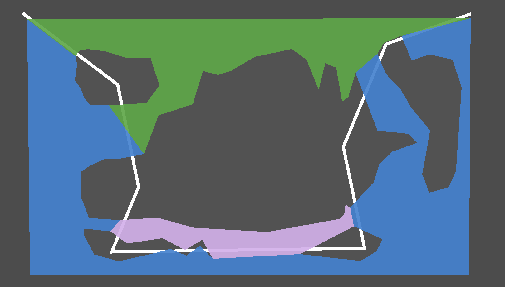
or this :

or this :

Depending on how you want to live your life.