I’m looking to replicate a flat shaded look where each face of a 3d object is uniformly lit and displays only one colour. This doesn’t require a shader when only using a DirectionalLight3D (presumably because it’s position is ignored) so long as the 3D object is flat shaded.
However when using positional lights (e.g. an OmniLight3D) this no longer works and the face may not be lit uniformly as each fragment will have a slightly different direction and distance to the light.
I think this might be easily solved if Vertex Lighting worked but it doesn’t. So I’ve been trying to work out whether it’s possible to do it in a shader instead. I think I understand the theory and what I want to achieve - basically I need each fragment on a face to use a single common position to calculate the light vector and attentuation from. Howver my inexperience with shaders means I haven’t got anywhere near a workable solution.
I’d appreciate any help or guidance on how to achieve this.
I would recommend altering the models directly, it’s a one-click operation in blender. Re-calculating normals as part of a shader is wasted work. Or are you talking about specular lighting?
Thanks for your response, no this isn’t about specular lighting. My current understanding is that selecting flat shading in a modelling program just makes the normals at each vertex of a face the same as the face normal. I’m struggling to see how that would solve my particular issue with lights that have a certain world position as I don’t see how that affects the light vector or attenuation values which I’m assuming are still being calculated per fragment. However I may well be missing something fundamental!
With the experiments I’ve done I think what I need is for LIGHT and ATTENUATION to be constant for each fragment of a particular face. Ideally they would be calculated from the nominal centre of the face somehow.
However I don’t know how to achieve this in a shader.
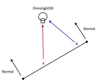
I’ve just made a little diagram which I think better illustrates what I’m getting at.
My current understanding is that point A and B on this face will not have the exact same light calculation and therefore this face will not be uniformly lit with a single colour regardless of how the normals are set up in the modelling program.
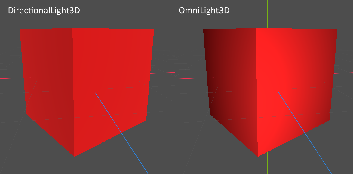
So I’ve just set up an experiment to try and simply show my problem. If I have a flat shaded cube (by setting Shade Flat in Blender) and import it into Godot it is indeed flat shaded when lit by a DirectionalLight3D. However if I then light it with an OmniLight3D instead you can see that there are obvious gradients on the faces. Basically, what I want to do is remove those gradients and have each face be a single colour. How can this be achieved?
I think maybe the solution is something to do with using the ‘flat’ interpolation qualifier on a varying to remove any interpolation of the fragments. But I can’t work out how to actually write the shader to do this. Any help would be massively appreciated!
But it will be per-triangle, and instead of the center it will use the position of the ‘provoking vertex’.
If you want it uniform across the face maybe you could massage your mesh data so that triangles of the same face will have the same provoking vertex?
Thanks for your response, this looks encouraging! I’m confused though, what is LIGHT_VERTEX in your code example? That doesn’t exist in spatial shaders.
Yeah, it’s new for 4.3. There doesn’t seem to be any equivalent in 4.2.2 so I’m guessing it’s not possible to do it this way (or maybe any other way?) in previous versions because you can’t write to the VERTEX value in the fragment shader.
Tried your solution in 4.3 and intriguingly I am getting the faces to be single uniform colours using the same cube from my previous experiments. Out of interest was your cube created in Godot? I guess that could potentially explain the difference as otherwise I’ve no idea why I’m not seeing the triangles.
Regardless this seems to be working fine and is exactly what I was looking for - thanks so much for your help . Kind of annoying that I spent a while banging my head against a wall with 4.2.2 when the easy solution was just to upgrade haha! Part of me still wonders whether there is a way to do this with previous versions.
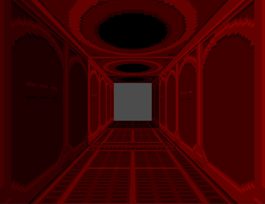
So I’ve been playing around with this some more and it looks like the fact the calculation is based on a provoking vertex causes problems. Here’s a corridor made of 3 ‘tiles’ which are just made of 4 square planes each. The light is located in the centre of the centre tile. The lighting is not as expected because the far tile has its left face lit with the same brightness as the faces of the centre tile and the nearest tile has all it’s faces except the left face lit this way. I’m assuming this is because, with the walls for example, on the left side each provoking vertex is on the edge of the tile nearest the camera, whereas on the right side each provoking vertex is on the edge of the tile furthest from the camera.
Massaging the mesh data wouldn’t help in this case as all the vertices are in the corners of those faces anyway and I’m guessing there is no way to use the centre of the face to do the calculations as the shader doesn’t have a concept of the faces to start with, it only works with primitives? The only thing I can currently think to do is to subdivide the meshes to get the light to spread better. If anyone has any better ideas or insights do let me know!
EDIT: The more I think about this the more I wonder whether this would be better achieved by scripting an entire fake lighting system that doesn’t use actual lights or shaders at all…
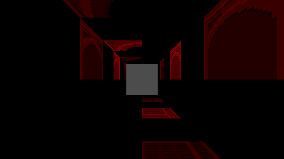
So I decided to try subdividing the meshes once so that there is a new vertex in the centre of each original face. I then assigned a specific vertex colour to those central vertices in Blender. I then get the shader to only calculate the ‘flat_vertex’ when the COLOR matches the colour I assigned to those central vertices. This results in the following which seems to be working in the sense that I’m pretty sure the primitives that are lit are being lit correctly from the centre of the original faces.
However there is obviously an issue where three quarters of the triangles aren’t being lit at all. I’m unsure why that would be as surely they all share that vertex at the centre? Are there actually four separate vertices at that central location and, if so, how do I assign the vertex colour to all of them? Once again, any assistance would be massively appreciated - it feels like I’m close now!
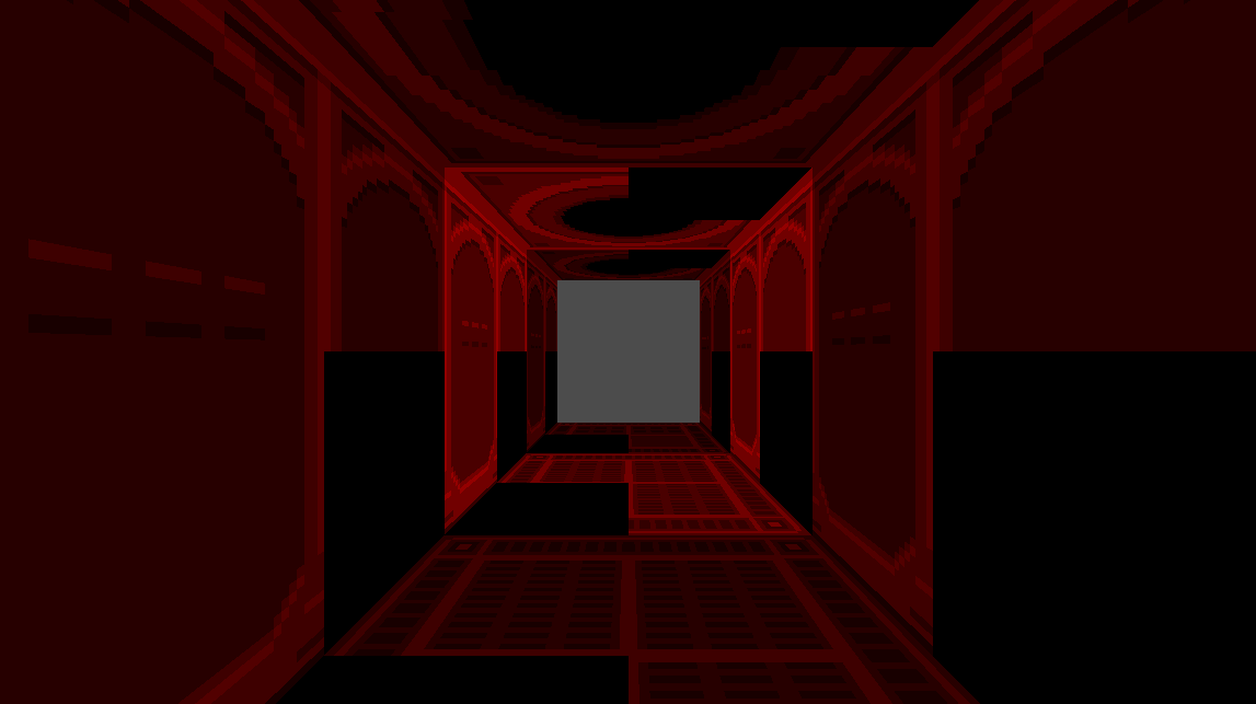
Well it was obviously incorrect to assume that the triangles were all sharing the central vertex as I was letting Godot arbitrarily triangulate the mesh! So I went back into the Blender and triangulated it manually so now every triangle on each ‘face’ of a tile definitely shares that central vertex.
I now get this in Godot. So it’s an improvement again as now three quarters of the triangles are lit correctly but obviously there’s still a quarter that aren’t. In fact it is also worse than I thought because it turns out those ‘unlit’ tris are unstable, they will flicker and their light level will increase the closer the camera gets to them. This seems odd to me, why would only those triangles act like that and how is their lighting now somehow dependent on the view? The instability is entirely introduced by adding an if statement to check the vertex colours. I’d assumed it would be as simple as checking whether a vertex was a certain colour (red in this case) and then passing only that vertex into the flat varying to be used in the fragment shader but I guess I must be missing something. This is my code for the vertex function:
What’s interesting is if I remove the if statement and go back to the original code it looks like the following. So it would appear that by chance with this new subdivided and manually triangulated mesh the provoking vertex of three quarters of the tris is the central vertex anyway and the final two tris have their provoking vertex in the corner. Of note is that the correct and problematic tris are identical here as when I am including the vertex colour check… I’m unsure what that means. Even with the if statement is the shader somehow still reliant on the provoking vertices?
@Tir Sorry to bother you but as it was your assistance that set me on the correct path in the first place I was wondering whether you have any insight as to what is happening here and how I might be able correct it?
I’m out of my depth, but my limited understanding was the provoking vertex was either the first or last provided index (depending on api and settings) for the primitive in the index buffer, and I wouldn’t expect the vertex shader to be able to overwrite that the way you want to. I don’t really know what happens if you just don’t assign to a varying like that, but if it’s introducing seemingly random flickering I’d guess it’s using uninitialized memory, and the ones where it’s not flickering just happen to work out by chance. Otherwise maybe it’s auto-generated LODs (can disable in mesh import settings) having different vertex orders, or z-fighting from overlapping geometry.
I think there’s a way to get custom per-vertex attribute data to the shader (but I’ve never used this feature in godot), and using that you could provide all 3 vertices with the same data and then flat interpolation wouldn’t be necessary, but you’d have to preprocess the mesh to include that, maybe with an import script.
Yeah, it’s definitely not LODs as I realised that was an issue earlier with these pre-subdivided meshes and disabled their generation. I’m also pretty sure it’s not z-fighting as it occurs with just a single mesh.
Seems to me the odd behaviour is most likely because those primitives don’t have the varying assigned to them (presumably because their provoking vertex is not coloured red) like you say. It makes sense that the other primitives work fine because they look identical to when I’m not checking the vertex colour which must indicate their provoking vertex is the central one (which is coloured red so the varying is assigned as expected).
So, if I’m understanding correctly, the issue here is that the varyings are assigned per vertex regardless of what I write in the vertex function? (I think I was imagining that they existed independently) So with the current code for each primitive two out of the three vertices have the varying essentially set to nothing. So, similar I think to what you mention, a solution would be to set the varying to the same value for each vertex, i.e. the value based on the central vertex. But I’m guessing there isn’t a way to do that within the shader because we don’t have control of what order the vertices are processed in? So you can’t, for example, work out what the varying should be first based on the central vertex and then set the varying to that value for all three vertices.
I’m guessing this is why you then mention about passing per-vertex data to the shader from, I assume, outside. So do you mean having data at each vertex that isn’t the central one essentially referring to the central one? I don’t think I understand yet how that would work but I will do some more research!
Thanks again for engaging with me on this, much appreciated!
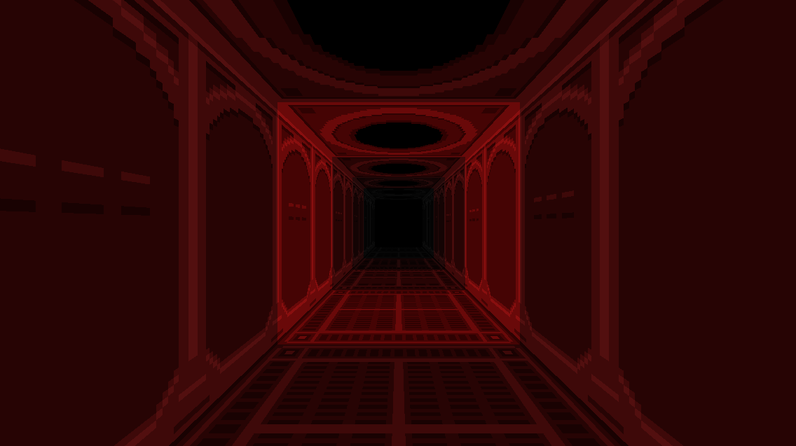
In case anyone is interested I have now solved the specific issue with the corridor example. The advantage of this solution is there is no need to subdivide the mesh to get a new vertex at the centre of the faces and no need for vertex colours.
Instead I am simply using a uniform vec3 in the vertex function in place of VERTEX. I manually set this uniform in the material for each face to describe where the centre of that face is in local coordinates. So for example in this case the centre of the ceiling face is (0,1,0), the floor is (0,-1,0) etc. The only disadvantage is this does mean each face needs its own material but, in my case, this only required one additional material to separate the walls.
I don’t think this is any kind of general purpose solution and I’m sure there’s a better way of doing it but it has solved this specific issue so it will do for now! I think it’s likely this way of manually describing the centre of the faces is really only neccessary in certain circumstances when it becomes obvious that a provoking vertex is at the edge of a face, mostly when you have very large faces or a set of similar, large faces next to each other.