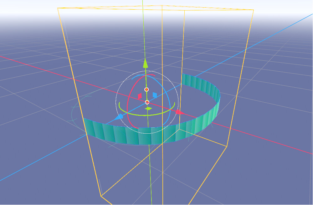
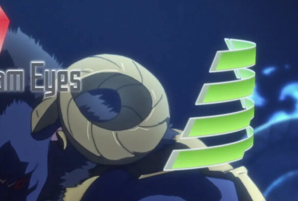
I couldn’t find a picture of what you’re talking about, but from what you describe:
Generated Code
shader_type spatial;
render_mode blend_mix, depth_draw_opaque, cull_disabled, diffuse_lambert, specular_schlick_ggx;


// Varyings
varying vec3 var_WorldPos;

uniform sampler2D OriginalTexture : source_color;
uniform float DissolveHeight = 0.0;
uniform float NoiseScale;
uniform float NoiseSize : hint_range(0.0, 500.0, 1.0) = 10.0;
uniform float GlowThickness = 0.01999999955297;
uniform vec4 EdgeColor : source_color = vec4(0.130000, 3.243000, 2.162000, 1.000000);


// PerlinNoise3D

		vec3 mod289_3(vec3 x) {
			return x - floor(x * (1.0 / 289.0)) * 289.0;
		}

		vec4 mod289_4(vec4 x) {
			return x - floor(x * (1.0 / 289.0)) * 289.0;
		}

		vec4 permute(vec4 x) {
			return mod289_4(((x * 34.0) + 1.0) * x);
		}

		vec4 taylorInvSqrt(vec4 r) {
			return 1.79284291400159 - 0.85373472095314 * r;
		}

		vec3 fade(vec3 t) {
			return t * t * t * (t * (t * 6.0 - 15.0) + 10.0);
		}

		// Classic Perlin noise.
		float cnoise(vec3 P) {
			vec3 Pi0 = floor(P); // Integer part for indexing.
			vec3 Pi1 = Pi0 + vec3(1.0); // Integer part + 1.
			Pi0 = mod289_3(Pi0);
			Pi1 = mod289_3(Pi1);
			vec3 Pf0 = fract(P); // Fractional part for interpolation.
			vec3 Pf1 = Pf0 - vec3(1.0); // Fractional part - 1.0.
			vec4 ix = vec4(Pi0.x, Pi1.x, Pi0.x, Pi1.x);
			vec4 iy = vec4(Pi0.yy, Pi1.yy);
			vec4 iz0 = vec4(Pi0.z);
			vec4 iz1 = vec4(Pi1.z);

			vec4 ixy = permute(permute(ix) + iy);
			vec4 ixy0 = permute(ixy + iz0);
			vec4 ixy1 = permute(ixy + iz1);

			vec4 gx0 = ixy0 * (1.0 / 7.0);
			vec4 gy0 = fract(floor(gx0) * (1.0 / 7.0)) - 0.5;
			gx0 = fract(gx0);
			vec4 gz0 = vec4(0.5) - abs(gx0) - abs(gy0);
			vec4 sz0 = step(gz0, vec4(0.0));
			gx0 -= sz0 * (step(0.0, gx0) - 0.5);
			gy0 -= sz0 * (step(0.0, gy0) - 0.5);

			vec4 gx1 = ixy1 * (1.0 / 7.0);
			vec4 gy1 = fract(floor(gx1) * (1.0 / 7.0)) - 0.5;
			gx1 = fract(gx1);
			vec4 gz1 = vec4(0.5) - abs(gx1) - abs(gy1);
			vec4 sz1 = step(gz1, vec4(0.0));
			gx1 -= sz1 * (step(0.0, gx1) - 0.5);
			gy1 -= sz1 * (step(0.0, gy1) - 0.5);

			vec3 g000 = vec3(gx0.x, gy0.x, gz0.x);
			vec3 g100 = vec3(gx0.y, gy0.y, gz0.y);
			vec3 g010 = vec3(gx0.z, gy0.z, gz0.z);
			vec3 g110 = vec3(gx0.w, gy0.w, gz0.w);
			vec3 g001 = vec3(gx1.x, gy1.x, gz1.x);
			vec3 g101 = vec3(gx1.y, gy1.y, gz1.y);
			vec3 g011 = vec3(gx1.z, gy1.z, gz1.z);
			vec3 g111 = vec3(gx1.w, gy1.w, gz1.w);

			vec4 norm0 = taylorInvSqrt(vec4(dot(g000, g000), dot(g010, g010), dot(g100, g100), dot(g110, g110)));
			g000 *= norm0.x;
			g010 *= norm0.y;
			g100 *= norm0.z;
			g110 *= norm0.w;
			vec4 norm1 = taylorInvSqrt(vec4(dot(g001, g001), dot(g011, g011), dot(g101, g101), dot(g111, g111)));
			g001 *= norm1.x;
			g011 *= norm1.y;
			g101 *= norm1.z;
			g111 *= norm1.w;

			float n000 = dot(g000, Pf0);
			float n100 = dot(g100, vec3(Pf1.x, Pf0.yz));
			float n010 = dot(g010, vec3(Pf0.x, Pf1.y, Pf0.z));
			float n110 = dot(g110, vec3(Pf1.xy, Pf0.z));
			float n001 = dot(g001, vec3(Pf0.xy, Pf1.z));
			float n101 = dot(g101, vec3(Pf1.x, Pf0.y, Pf1.z));
			float n011 = dot(g011, vec3(Pf0.x, Pf1.yz));
			float n111 = dot(g111, Pf1);

			vec3 fade_xyz = fade(Pf0);
			vec4 n_z = mix(vec4(n000, n100, n010, n110), vec4(n001, n101, n011, n111), fade_xyz.z);
			vec2 n_yz = mix(n_z.xy, n_z.zw, fade_xyz.y);
			float n_xyz = mix(n_yz.x, n_yz.y, fade_xyz.x);
			return 2.2 * n_xyz;
		}


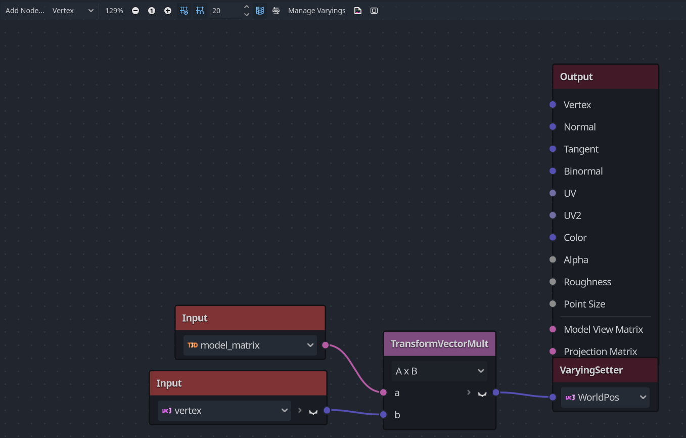
void vertex() {
// Input:4
	mat4 n_out4p0 = MODEL_MATRIX;


// Input:3
	vec3 n_out3p0 = VERTEX;


// TransformVectorMult:5
	vec3 n_out5p0 = (n_out4p0 * vec4(n_out3p0, 1.0)).xyz;


// VaryingSetter:2
	var_WorldPos = n_out5p0;


}

void fragment() {
	vec4 n_out24p0;
// Texture2D:24
	n_out24p0 = texture(OriginalTexture, UV);


// FloatParameter:7
	float n_out7p0 = DissolveHeight;


// FloatParameter:14
	float n_out14p0 = NoiseScale;


// VaryingGetter:4
	vec3 n_out4p0 = var_WorldPos;


// FloatConstant:12
	float n_out12p0 = 0.000000;


// FloatParameter:13
	float n_out13p0 = NoiseSize;


	float n_out11p0;
// PerlinNoise3D:11
	{
		n_out11p0 = cnoise(vec3((n_out4p0.xy + vec3(n_out12p0).xy) * n_out13p0, n_out12p0)) * 0.5 + 0.5;
	}


// FloatOp:16
	float n_out16p0 = n_out14p0 * n_out11p0;


// FloatOp:15
	float n_in15p1 = 0.50000;
	float n_out15p0 = n_out14p0 * n_in15p1;


// FloatOp:17
	float n_out17p0 = n_out16p0 - n_out15p0;


// VectorDecompose:5
	float n_out5p0 = n_out4p0.x;
	float n_out5p1 = n_out4p0.y;
	float n_out5p2 = n_out4p0.z;


// FloatOp:18
	float n_out18p0 = n_out17p0 + n_out5p1;


// Step:9
	float n_out9p0 = step(n_out7p0, n_out18p0);


// FloatFunc:10
	float n_out10p0 = 1.0 - n_out9p0;


// FloatParameter:3
	float n_out3p0 = GlowThickness;


// FloatOp:19
	float n_out19p0 = n_out7p0 - n_out3p0;


// Step:20
	float n_out20p0 = step(n_out19p0, n_out18p0);


// ColorParameter:21
	vec4 n_out21p0 = EdgeColor;


// VectorOp:22
	vec3 n_out22p0 = vec3(n_out20p0) * vec3(n_out21p0.xyz);


// FloatConstant:6
	float n_out6p0 = 0.500000;


// Output:0
	ALBEDO = vec3(n_out24p0.xyz);
	ALPHA = n_out10p0;
	EMISSION = n_out22p0;
	ALPHA_SCISSOR_THRESHOLD = n_out6p0;


}