I have this VERY minimal shader code - attempting to use a Red/Green image to displace pixels in the actual texture by feeding the red/green values in place of the UV. It generally works, but it comes out blurred/garbled and I’m not sure why.
uniform sampler2D displacement_map;

void fragment() {
	vec4 map_color = texture(displacement_map, UV);
	COLOR = texture(TEXTURE, map_color.rg);
//	COLOR = map_color;
}
For now, I have a basic 0 to 1 Red/Green gradient image loaded as displacement_map. If I uncomment the last line, that gradient comes out perfectly smooth. But when I try to output the image using the map_color.rg, it’s a mess. I’ve done a bunch of experiments with filter_nearest/filter_linear but it doesn’t really change. I haven’t managed to find an example of a similar simple shader – it seems like there’s just some simple thing I’m misunderstanding about how this should work.
The end result I’m hoping for is to use a modified red/green image to affect the original image.
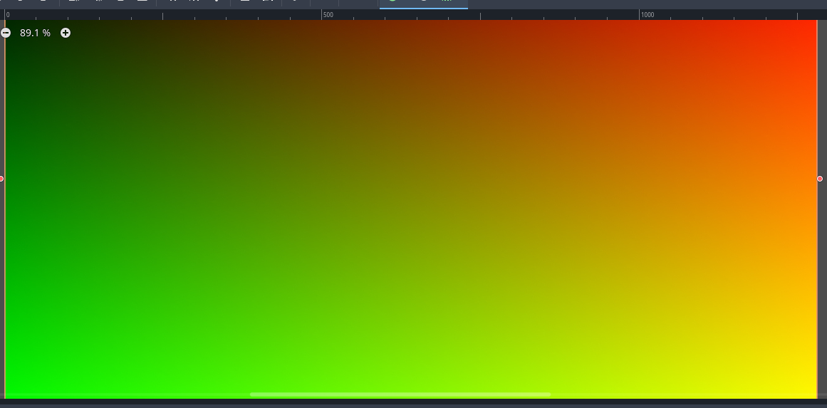
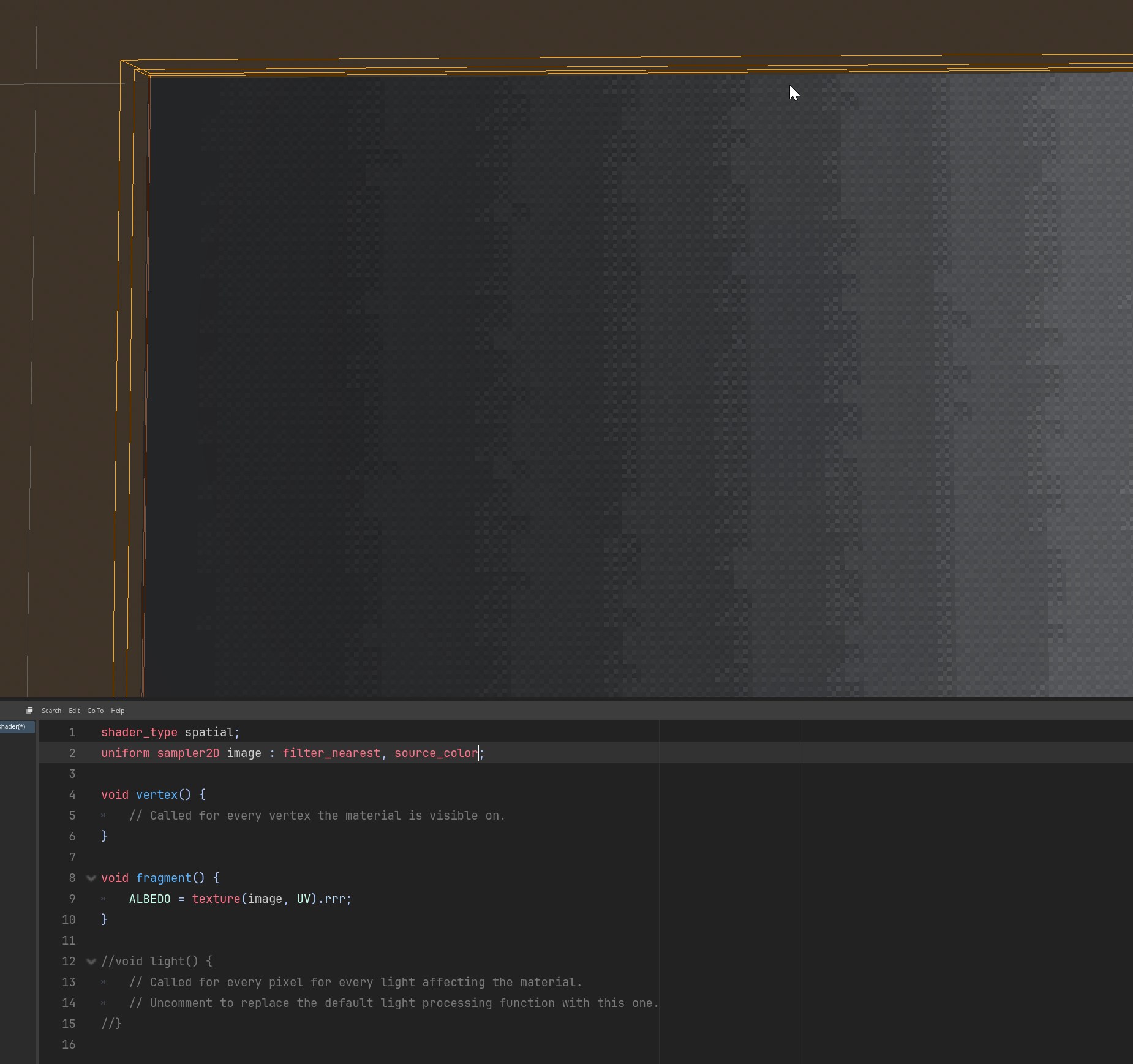
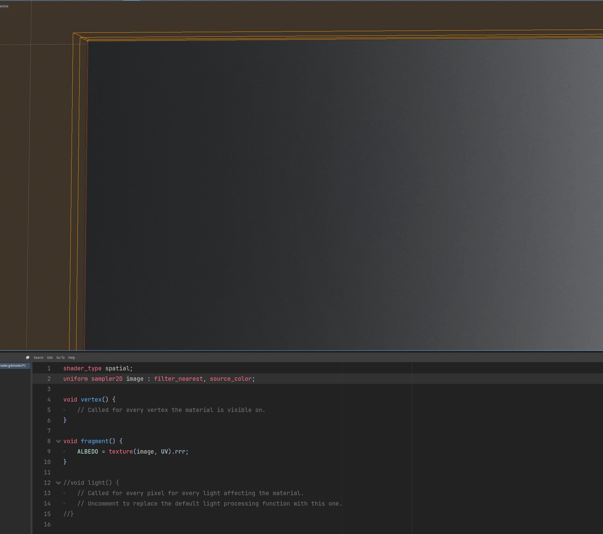
This is what it looks like in the editor with the last line uncommented
I would imagine it’s just compression on that displacement_map texture, so if you are remapping one texture using another, per pixel the values will be chaotic. You can try removing any texture compression on the displacement_map texture and see what that does for you.
If it is the compression on that texture, and if you still want to use a texture like that and make it uncompressed, best thing to do is just try and reduce the size of that textures as much as you can to reduce the memory cost as uncompressed textures can be a hog.
What is your ultimate goal to need a UV displacement texture?
I did notice that it’s a “compressed2d” texture in the editor - but if I output the pixels of “map_color” as in the first image, the gradient is super smooth; that’s why I’m so confused about why the output turns to noise if I use those R/G values for the UV on the TEXTURE. It’s also not just like … ‘banded’ as if it’s a low quality gradient, it’s just noise/mush on the output.
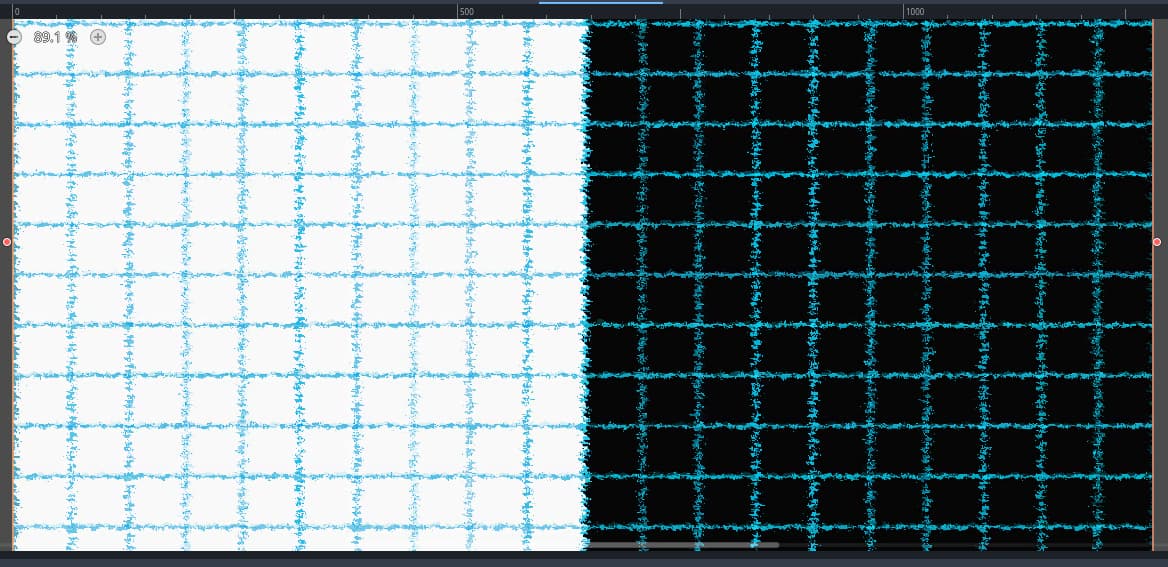
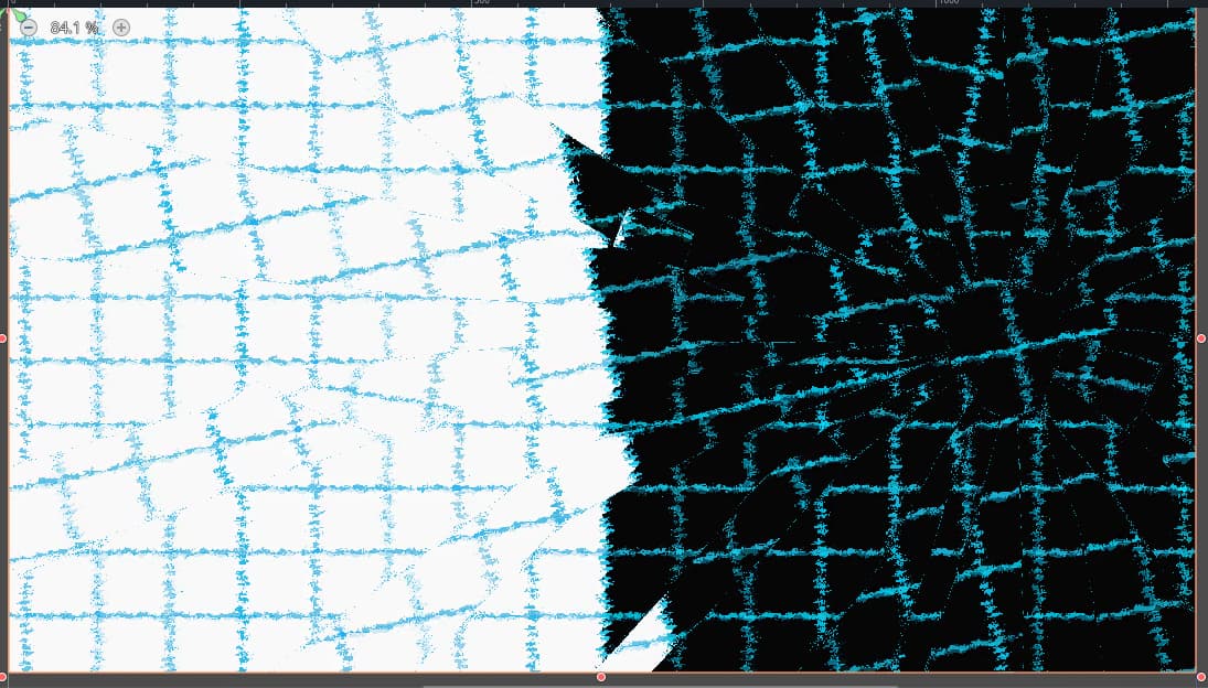
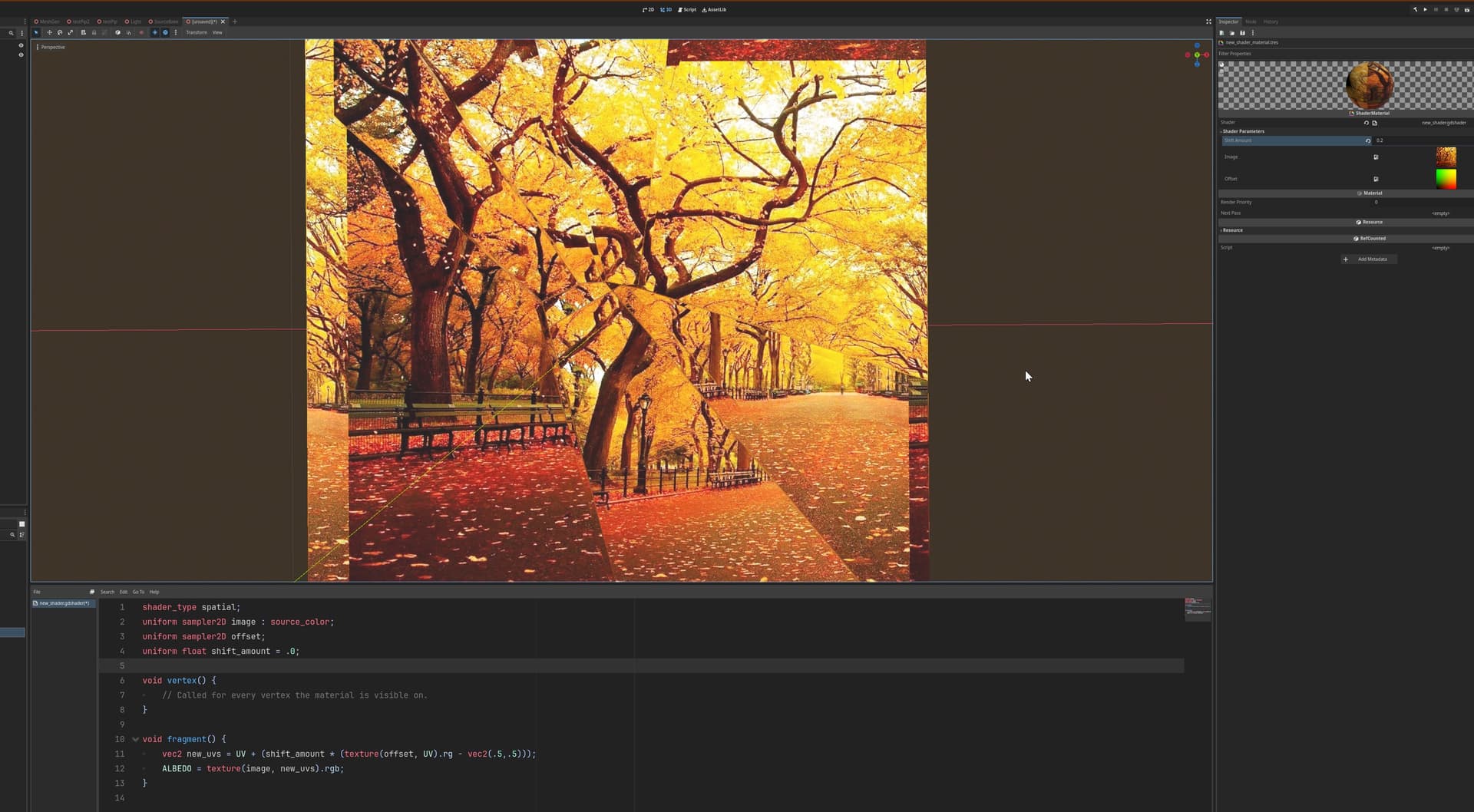
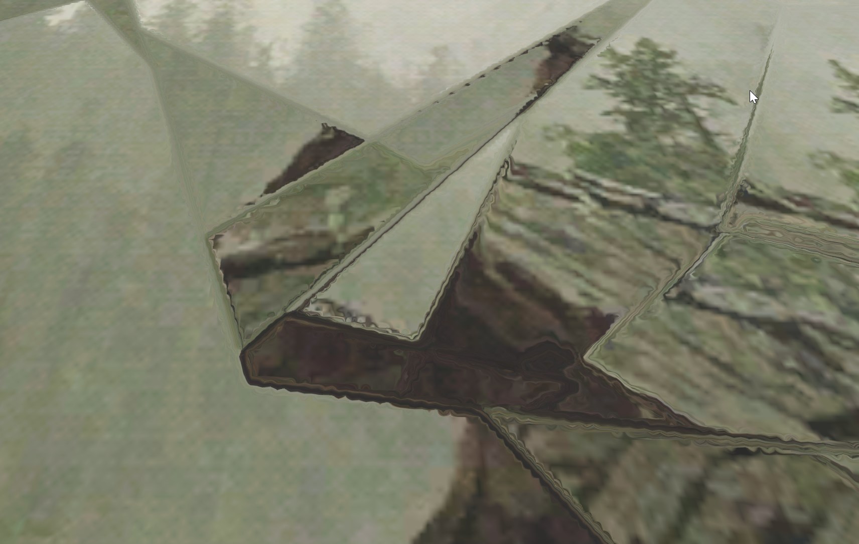
The end result I’m trying to get is being able to make the source look like it’s behind cracked glass. I have a R/G image styled like that, and it works - if I could just get rid of the weird blurring.
Here’s the ‘cracked glass’ version - with the same blurry result.
When you say it looks super smooth, are you saying when you visually look at that displacement_map texture in godot? Also, are you saying that it looks that weird when that texture is set to no compression?
I am just thinking if there is any slight aberration in the values from pixel to pixel on that displacement_map, it shifts the mapping more than you’d think. Try a test, downrez your texture by like 1/8th, and then see the result of it on that grid.
This is the Resource type, which can store various compression types (including lossless compression and uncompressed). It doesn’t have a direct relationship as to whether the compression used is lossy.
Check the Import dock for the actual value of the compression mode used. For this kind of shader textures, you want it to be Lossless.
Thanks - I had to do some digging around to find the import settings you mentioned, I just hadn’t ever looked for them before. It is set to lossless, and I tried adjusting a ton of the various options and re-importing with no change in output.
Thanks for the input. I tried scaling it down to 1/10th, and the lines do get smoother (still not clean though), but of course it loses detail.
I thought this should just work as ‘lookup table’ of sorts - both the image I’m warping and the displacement are the same size, so I thought I could just take the Red/Green values at the location of the displacement UV and use that as a ‘lookup’ for which pixel to pull from the TEXTURE in that spot - like if the UV is (0.1, 0.1) and the RG value on the displacement image at that UV coordinate is (0.15, 0.2) I thought I could just tell COLOR to use the TEXTURE color at (0.15, 0.2) in place of (0.1, 0.1); apparently it just doesn’t work like that?
Even with 8 bit textures, not even compressed, will give you either dithering or banding across the gradients you have on the R and G channel of that texture.
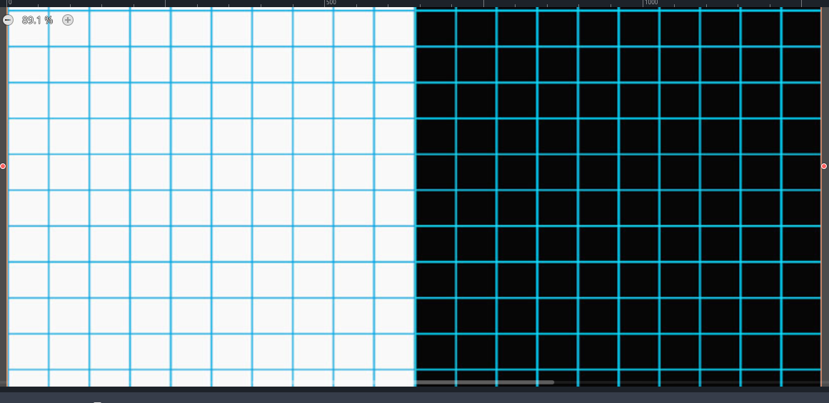
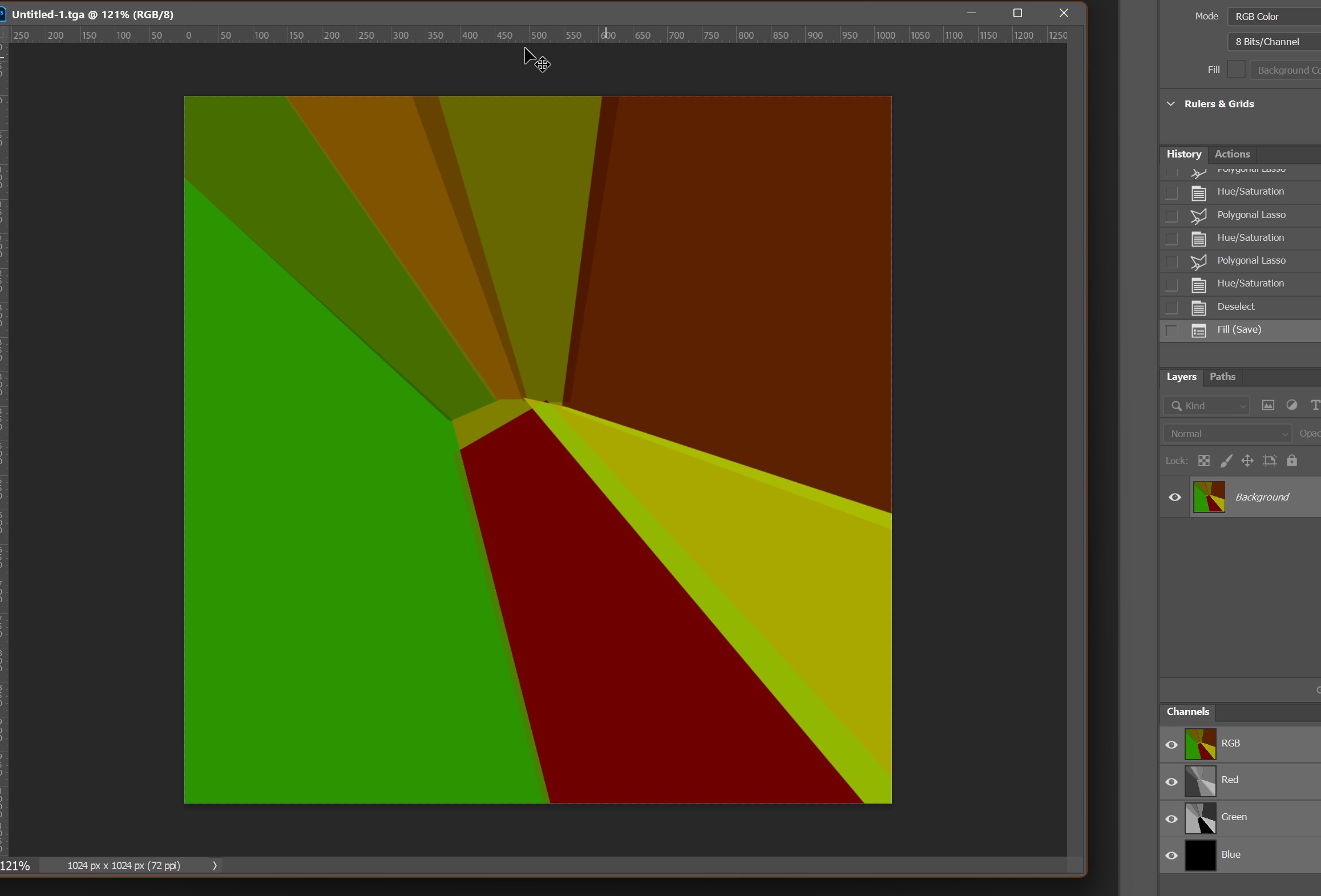
The first image here is an 8 bit gradient created in photoshop, this is the top right corner of the R channel, and you can see a lot of noise.
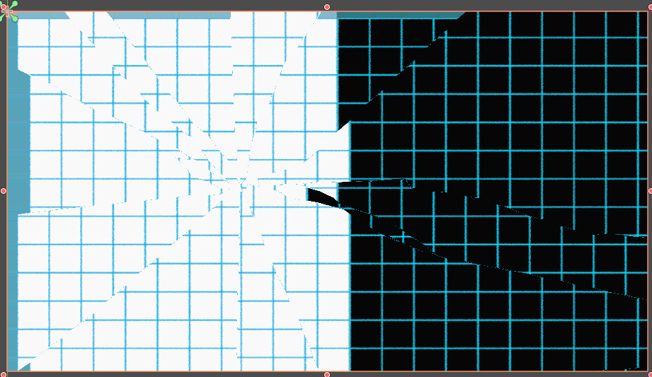
So that imported into Godot will look like below when I make a shader that only shows the R channel and it being nearest filtered so you can see the massive changes from pixel to pixel, so then if you imagine those are your UV’s, going from left to right, the image mapping will be pushed around, up and down and all around and not just a smooth, clean ramp up the whole time.
So unless you create your gradient as a 32 bit source image, you won’t be able to get a smooth gradient, and I don’t even know if godot supports 32 bit textures.
What I would try is making your texture an ‘offset’ texture that uses the base UV’s of your mesh or surface, and then the pixels of the texture just offset those UV’s, so you’d paint the unbroken chunks of broken glass with how much you’d want to offset the texture mapping per chunk. That way the texture isn’t your full source of your new UV’s, it’d just need some flat colors that represent a relative ‘push’ in the U or V based on the R and G values. For instance you could do it where .5 on the texture does not offset the surface UV’s at all, and if you add values above .5, it pushes the UV’s in a positive direction, and a value under .5 would push the UV’s in a negative direction.
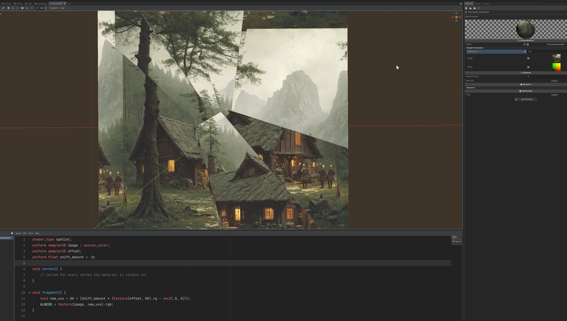
Here is an example:
First here is the offset texture:
This is all great info - thanks so much for taking the time. The only slight downside is that as it pulls away from and edge you get a smear of whatever would be at the edge (maybe I could fix that with some fancy math?) - but this is workable.
For the record, I did try a 32 bit gradient and that was still a bit messy - the solid colors to use as a shift is the real answer.
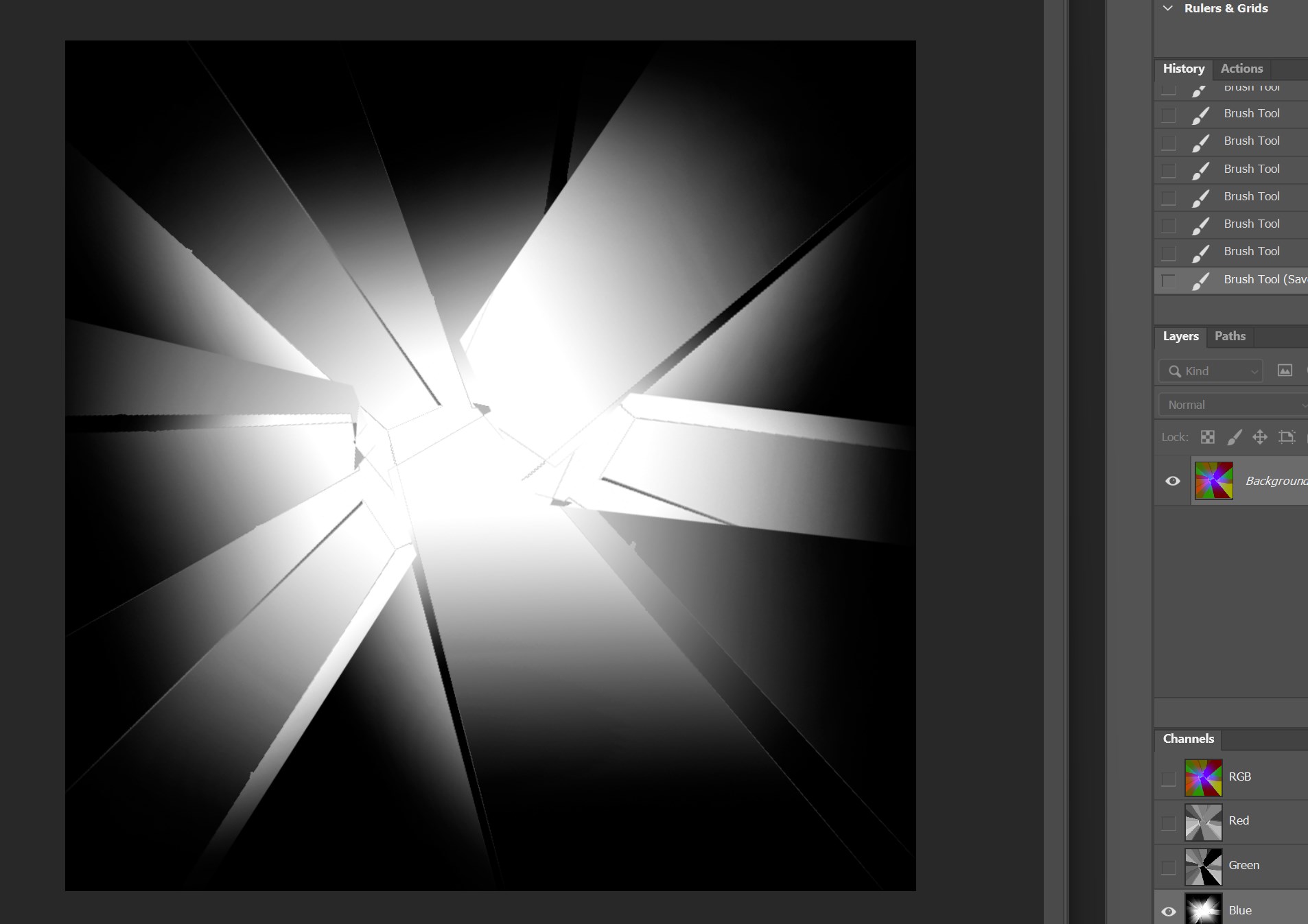
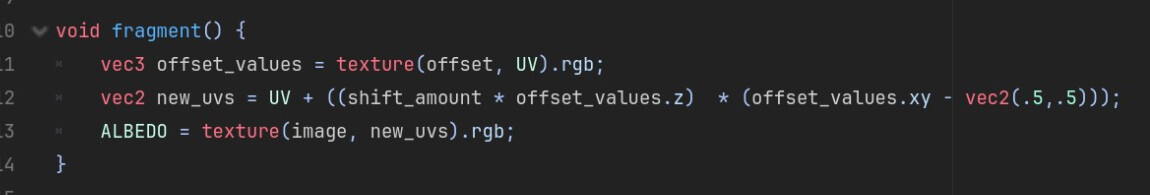
If I think I get what you are referring to, meaning the pulling away on the edge of the ‘glass pane’, the last two images shows a possible fix using the B channel to pin the offset at the edges of the pane. Actually as I look at my solution, I could have done that pinning in the R and G channels too
Kind of, as a test paint a vignette type gradient in the B channel of the same texture you are using to offset the UV’s, should be where the edges are black and then they slowly go to white in the center, a nice gradient, just make sure the edges are completely black by the time the gradient gets there.
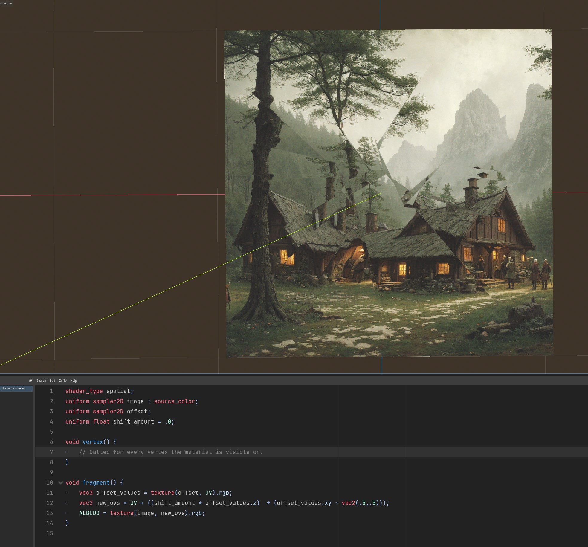
Multiply your offset math by the B channel of the offset texture (z of offset_values here), and then add that to the existing UV’s, see if that helps. I have the shift amount in there, but you don’t need it really.
This should replicate the glass shards still being pinned to the window frame, and then kind of angling forward and backwards away from the plane of the window.